• McIntosh Laboratory, Inc. 2 Chambers Street Binghamton, New York Phone: 607-723-3512 www.mcintoshlabs.com MX151 A/V Control Center Owner’s Manual Manufactured under license from Dolby Laboratories. Dolby, Pro Logic and the double-D symbol are trademarks of Dolby Laboratories. Manufactured under license from Lyngdorf Au- Manufactured under license dio A/S.
• The lightning flash with arrowhead, within an equilateral The exclamation point within an equilateral triangle is triangle, is intended to alert the user to the presence of intended to alert the user to the presence of important uninsulated “dangerous voltage” within the product’s en- operating and maintenance (servicing) instructions in the closure that may be of sufficient magnitude to constitute literature accompanying the appliance. • Thank You Customer Service Remote Control: Your decision to own this McIntosh MX151 A/V Con- If it is determined that your McIntosh product is in trol Center ranks you at the very top among discrimi- need of repair, you can return it to your Dealer. You Remote Control Push-buttons. • General Information General Information 1. For additional connection information, refer to the 8.
Baby & children Computers & electronics Entertainment & hobby Fashion & style Food, beverages & tobacco Health & beauty Home Industrial & lab equipment Medical equipment Office Pet care Sports & recreation Vehicles & accessories.
MX151 is a two Zone Product (Zone A and Zone Video 2 Ouput, ZA Video Outputs and ZA S- owner’s manual(s) for any component(s) connect- B). This allows two different Audio/Video Sourc- Video Outputs will be muted. Tranceive Data (+) 5. N/C Below is the Pin configuration for the XLR Balanced The MX151 Data Out Ports send Remote Control Sig- 2. Tranceive Data (-) 6. Receive Data (-) Output Connectors on the MX151. Refer to the dia- nals to McIntosh Source Compo- 3.
• • Dual Zone excellence in a Home Theater System. The MX151 Decoders The MX151 has the built-in ability to control a sepa- provides superior multichannel reproduction, RoomP- The MX151 also provides built-in decoding of the rate remote audio/video zone with program selection. • Dimensions Dimensions The following dimensions can assist in determining the best location for your MX151.

Front View of the MX151 ' 44.45cm ' ' 19.37cm 18.10cm Side View of the MX151 ' 41.91cm ' 36.83cm ' 9/16 ' 3/16 16.67cm 0.48cm. Winning eleven 2012 for pc full version. • Installation Installation The MX151 can be placed upright on a table or ' 3/16 shelf, standing on its four feet.
It also can be custom 43.66cm installed in a piece of furniture or cabinet of your choice. The four feet may be removed from the bottom of the MX151 when it is custom installed as outlined below. • Rear Panel Connections Rear Panel Connections The identification of Rear Panel Connections for the MX151 A/V Control Center is located on a separate folded sheet contained in the Owner’s Manual Packet. Refer to separate sheet “Mc1A” for the Rear Panel Connections. • “Pr/R” to “Cr”. Data In jack. HDMI Connections: the system is possible when the MX151 is located in a cabinet with the doors closed (Zone A).
Connect a Control Cable from the MX151 DATA 17. Connect a HDMI Cable from the MX151 HDMI OUTPUT 7 Jack to the Music Server Data In jack.
• HDMI Connections: Power Control Connections: 10. Connect a HDMI Cable from the MX151 ZA 1.
WARN INDUSTRIES * WINCH. MOUNTING WINCH. MOUNTING WINCH. Choose a mounting location. That is suffi ciently strong enough to withstand the loads you intend to winch. Only the mounting orientations shown are possible for safe winching operation. All others are improper and inappropriate. This Warn Industries M12000 Series 12 volt electric Winch is vehicle mounted and has a pull capacity of 12,000 pound. It has a 125 feet wire rope. SERVICE MANUAL FOR THE MIL-9000 and MIL-12000. A Warn Industrial electric winch is a compact device used to pull large loads over long distances.
Connect a Control Cable from the MX151 ZA PC HDMI OUT Connector to the Zone A TV/Monitor (Power Control) OUT Jack to the Power Control In HDMI Input connector. • Power Control Connections: 2. Connect an Audio Cable from the MX151 STER- 1.
Connect a Control Cable from the MX151 ZB PC ERO AUDIO IN 1 Jacks to the AM/FM Tuner (Power Control) OUT Jack to the Power Control In unbalanced Output Jacks. • Selects one of the ten Mode available Audio Sources Use to scroll thru available inputs for Zone A and B; and phantom Inputs for Zone A Note: Push-buttons whose function is not identified above are for use with other McIntosh Products. • MX151 via the Data Ports. Push-button to seek the next available station. 7 Down Note: If at any time the MX151 seems unresponsive to Press and hold a Channel SEEK Up or Enhanced Remote Control Operation 7 Down.
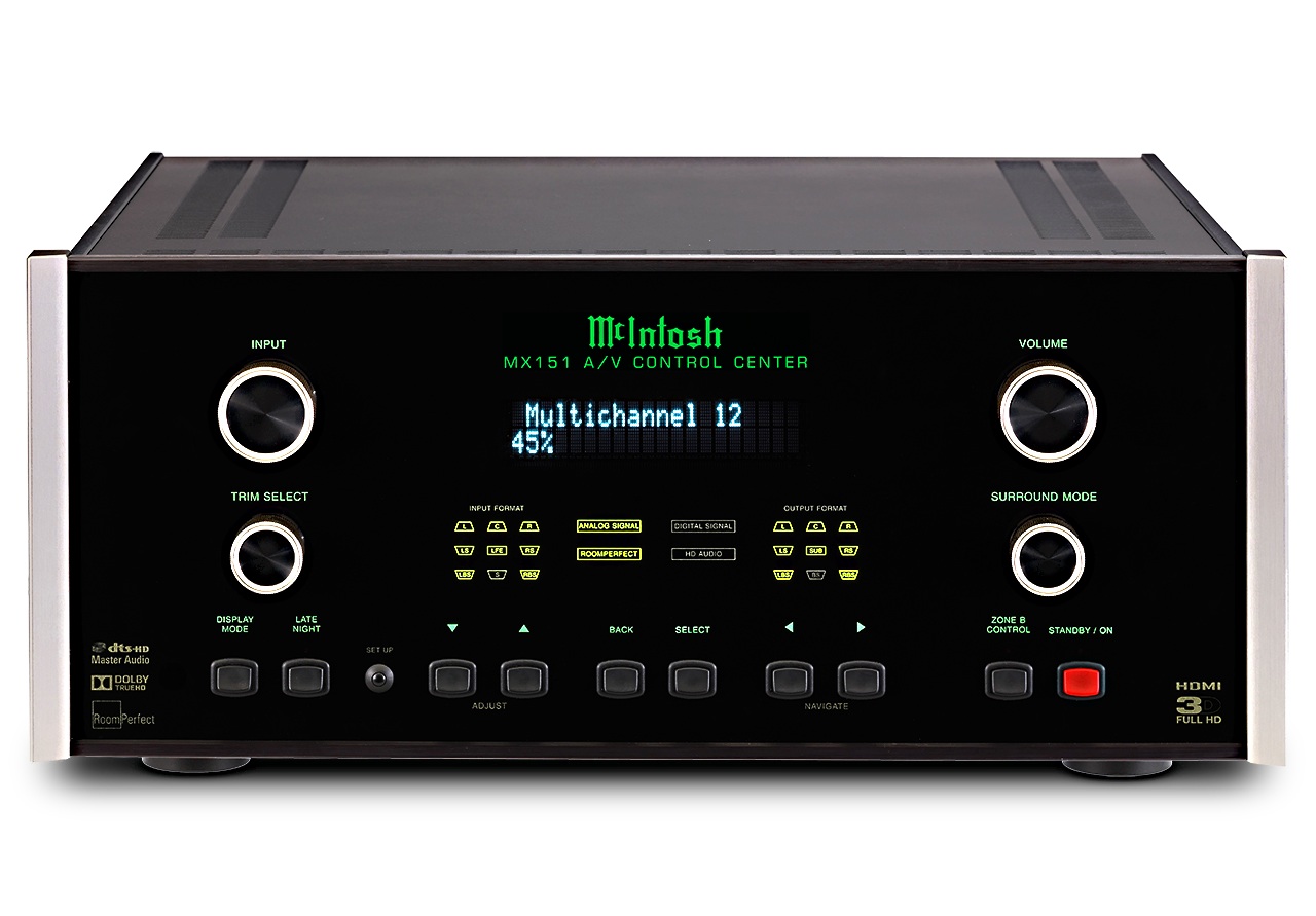
• Front Panel Display, Controls, and Push-buttons Front Panel Display, Controls, and Push-buttons The identification of the MX151 A/V Control Cen- ter Front Panel Display, Controls, and Push-buttons is located on a separate folded sheet contained in the Owner’s Manual Packet. Refer to separate sheet. • To assist in navigating the various On Screen ment (Menu) by press- “Installer Menu” will appear on the Front Panel Menus please refer to the set of MX151 Setup separate ing the Upp or Downq Information Display and the Installer Menu folded sheets contained in the Owner’s Manual Packet. • MENU SELECTION SETTING ADJUSTMENT SETTING PAGE MENU SELECTION SETTING ADJUSTMENT SETTING PAGE Speaker Zone A Configuration Source Size Input Name (Front and Surround) Video In HDMI 3 Bass perform Audio In Balanced 1 Bass cutoff 80Hz Audio Mode Music Bass order 4th LiRi Volume Offset 0.0dB. • Default Settings MENU SELECTION SETTING ADJUSTMENT SETTING PAGE MENU SELECTION SETTING ADJUSTMENT SETTING PAGE Zone A Zone A Source Source Input Name SERVER Input Name Video In Component 2 Video In None Audio In Digital 7 Opt.